Under förpackningsprocessen skickas produkten vanligtvis till mätanordningen för mätning med hjälp av en matningsanordning på förpackningsmaskinen, och fylls sedan i förpackningsbehållaren och lindas sedan in och förpackas.
Här introduceras den matningsanordning som vanligtvis används i förpackningsmaskinen och vakuumpumpen som används i vakuumförpackningsmaskinen. För den kvantitativa doseringsanordningen, se kapitlet om lastmaskinen. I avsnittet om förpackningsmaskinen introduceras också arbetsprinciperna och några typiska strukturella former för förpackningsbehållaren och matningsanordningen för förpackningsmaterial, fyllnings- och hällanordningen och omslags- och förpackningsanordningen.
Matningsanordning
Funktionen för matningsanordningen för förpackning av föremål är att mata föremålen som ska förpackas lagrade i magasinet till föremålsdoseringsanordningen för mätning enligt förpackningsprocesskraven, och sedan implementerar de andra enheterna i förpackningsmaskinen förpackningsoperationen.
Matningsanordningen för förpackning av föremål består i allmänhet av en tratt, en transportör, en matare, en antiblockeringsanordning, en sorterings- och riktningsanordning och en drivanordning. På grund av de stora skillnaderna i de fysiska och kemiska egenskaperna, naturliga formerna och kraven på förpackningsprocesser för föremålen, har matningsanordningen en mängd olika strukturella former.
Beroende på körläget för de levererade föremålen kan försörjningsanordningen delas in i: gravitationsmatningsanordning (inklusive gravitationstransport av färdiga föremål); bandtransportanordning (inklusive kedjetransportanordning); skruvtransportöranordning; pumpanordning; skivspelares glidanordning; vibrationsmatningsanordning etc.
Matningsanordningen bör ha en enkel struktur, tillförlitlig funktion, anpassa sig till de fysikaliska och kemiska egenskaperna hos materialet som matas och vara koordinerad med den efterföljande förpackningsprocessen.
Gravitationsmatningsanordning
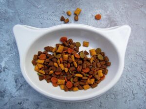
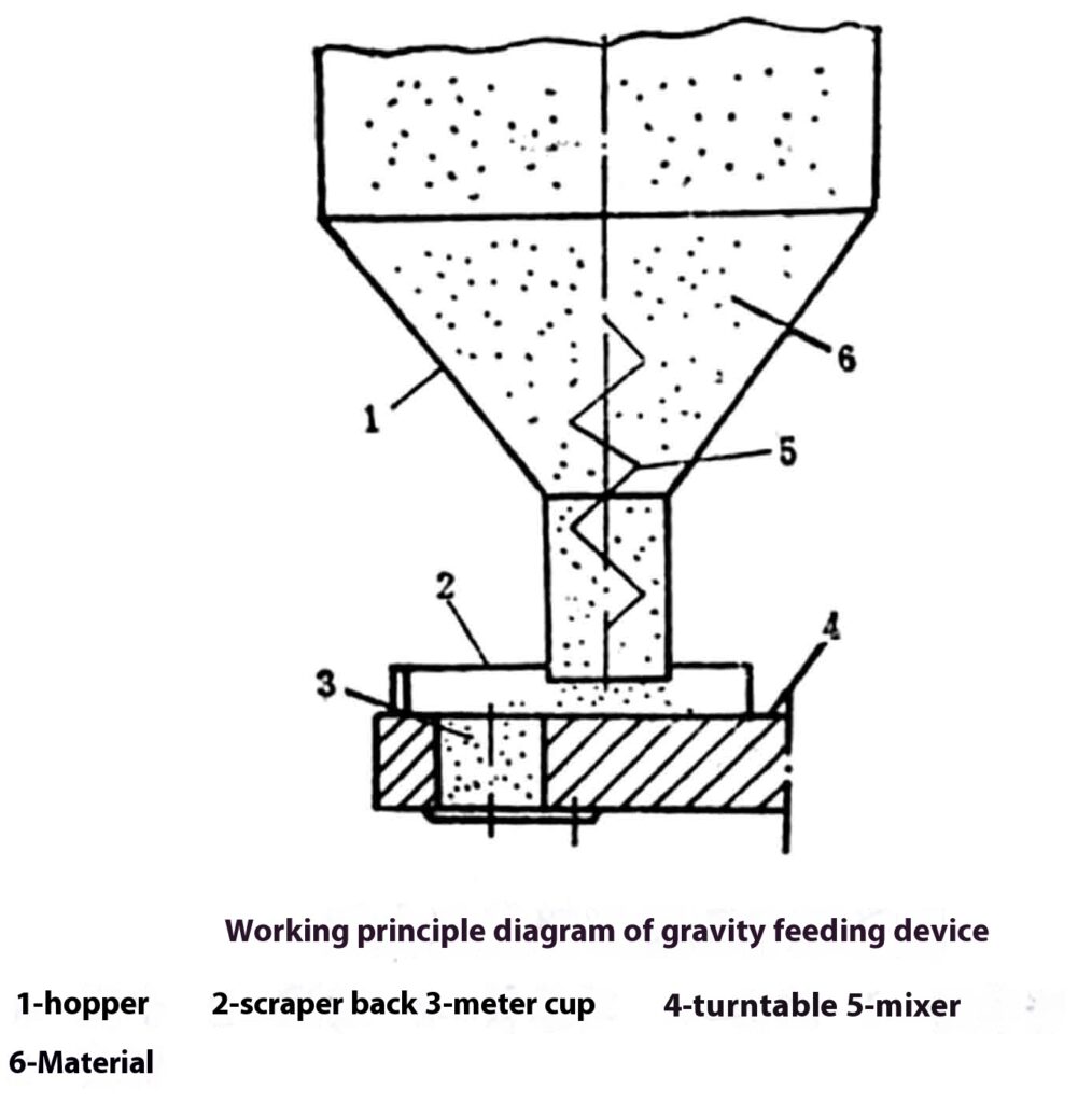
Tyngdkraftsmatningsanordningen använder egenskapen att föremålen kan flöda från högt till lågt under inverkan av gravitationen. Föremålen placeras i ett högt läge och flyter längs den fasta materialkanalen till det låga läget, varigenom försörjningen av föremålen realiseras. När föremålen flyter i materialkanalen är det lätt att bilda en båge eller bro, vilket resulterar i dåligt flöde eller till och med blockering. Därför bör flödeskanalen vara jämn och platt, och nödvändiga antiblockerande omrörningsanordningar bör ställas in. För föremål med riktningskrav bör även en sorterings- och riktningsanordning ställas in. Föremål som inte är lämpliga för automatisk orientering bör ordnas manuellt och staplas i behållaren i förväg.
Figuren är ett arbetsprincipdiagram av gravitationsmatningsanordningen för pulver och granulära material. Materialet i magasinet 1 strömmar kontinuerligt till den kvantitativa roterande skivan 4 under inverkan av sin egen vikt och omröraren 5, och den fasta skrapan 2 skrapar bort överskottsmaterialet på den roterande skivans doseringskopp 3, varigenom doseringsoperationen förverkligas.
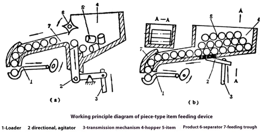
Matningsanordning för styckematerial
Figuren är ett principdiagram över matningsanordningen för styckematerial. Figur (a) visar en styckmaterialmatningsanordning som automatiskt kan välja och orientera, vilken är lämplig för automatisk matning av cylindriska stycken med relativt liten längd och diameter. De oordnade materialbitarna förvaras i behållaren. Under inverkan av orienteringsmekanismen 2 och avstötaren 6 är materialbitarna anordnade på ett riktat sätt i foderhon 7, och rör sig längs foderhoget till mataren 1 under inverkan av sin egen vikt, varigenom den intermittenta matningen av materialbitarna realiseras. Figur (b) visar en matningsanordning för bitar med relativt stor längd och diameter som inte är lätta att automatiskt välja och orientera. Materialbitarna måste placeras manuellt i behållaren i förväg. Under tyngden av materialbitarna och verkan av agitatorn 2, rör sig materialbitarna längs matarhon 7 till mataren 1, och mataren levererar materialbitarna till nästa process.
Bältesmatare
Bandmatare kan användas för leverans av bulk-, block-, säck- och styckegods och kan bestå av flera band för att möta olika förpackningsprocesskrav.
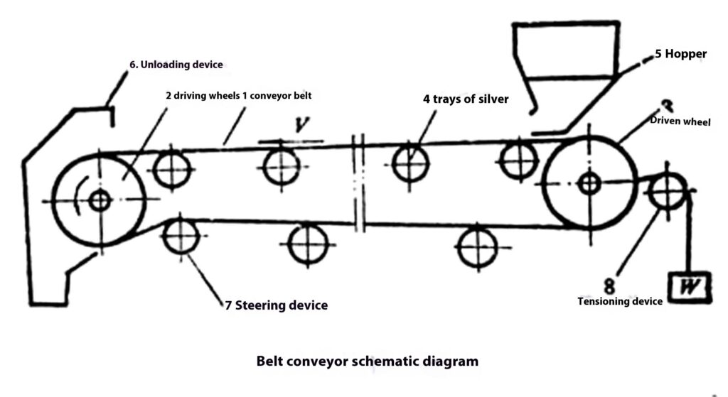
Figuren visar principdiagrammet för bandtransportören. Föremålen transporteras från magasinet 5 till avlastningsanordningen 6 och lossas. Spännanordningen 8 används för att justera bandets spänning, och styrrullen 7 används för att öka lindningsvinkeln för att säkerställa bandets transportkapacitet.
Transportbandet i bandmataren är i kontakt med föremålen. Enligt de fysikaliska och kemiska egenskaperna och hygienkraven för de transporterade föremålen måste motsvarande bandmaterial väljas och den nödvändiga fysiska och kemiska behandlingen måste utföras. Transportbandet inkluderar bomullsduksband, kemiskt fibertygsbälte, gummicanvasbälte, nylonplåtsband, stålband, metallnätband etc. Vanligt använda fysiska och kemiska behandlingsmetoder för bälten inkluderar impregnering, beläggning av ytskyddsskikt etc.
Kedjematningsanordning
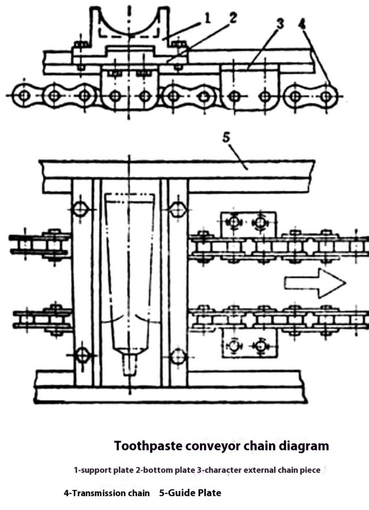
Figuren visar ett schematiskt diagram av en kedjetransportör för att transportera tandkräm på en tandkrämskartongermaskin. Grundstrukturen för en kedjetransportör som vanligtvis används för att mata förpackade föremål visas i figuren. Dragkomponenten för att transportera föremål består av två parallella ringkedjor. De två kedjorna är förbundna med ett litet skaft eller en spjäl för att hålla de två kedjorna parallella och på samma avstånd. Särskilda kedjeplattor installeras på kedjan, eller rullar och pallar installeras på den lilla axeln (ribban) mellan de två kedjorna. Tillbehör som tryckplattor används för att driva de förpackade föremålen att gå framåt. Dragkedjan använder i allmänhet en standardhylsrullkedja, eller en hylsrullkedja med en speciell lång kedjeplatta, en platt kedja etc. För att säkerställa korrekt ingreppsöverföring av kedjan och kedjehjulets tänder och matningens lägesnoggrannhet krävs i allmänhet en kedjespänningsanordning.
Kedjetransportörer är lämpliga för leverans av stycken och stjälkar som kräver exakt leverans av förpackade föremål och vissa förpackningsoperationer under transport.
Roterande skivmatningsanordning
När den roterande skivan roterar kan de material som lagras i skivbehållaren röra sig till ytterkanten av den roterande skivan under inverkan av friktion och centrifugalkraft, och är anordnade på ett riktat sätt längs skivans tangentriktning och kommer in i transportkanalen som tangerar skivans ytterkant. Genom att ställa in en viss transportanordning på transportkanalen kan den automatiska sorteringen och riktningsarrangemanget av material realiseras.
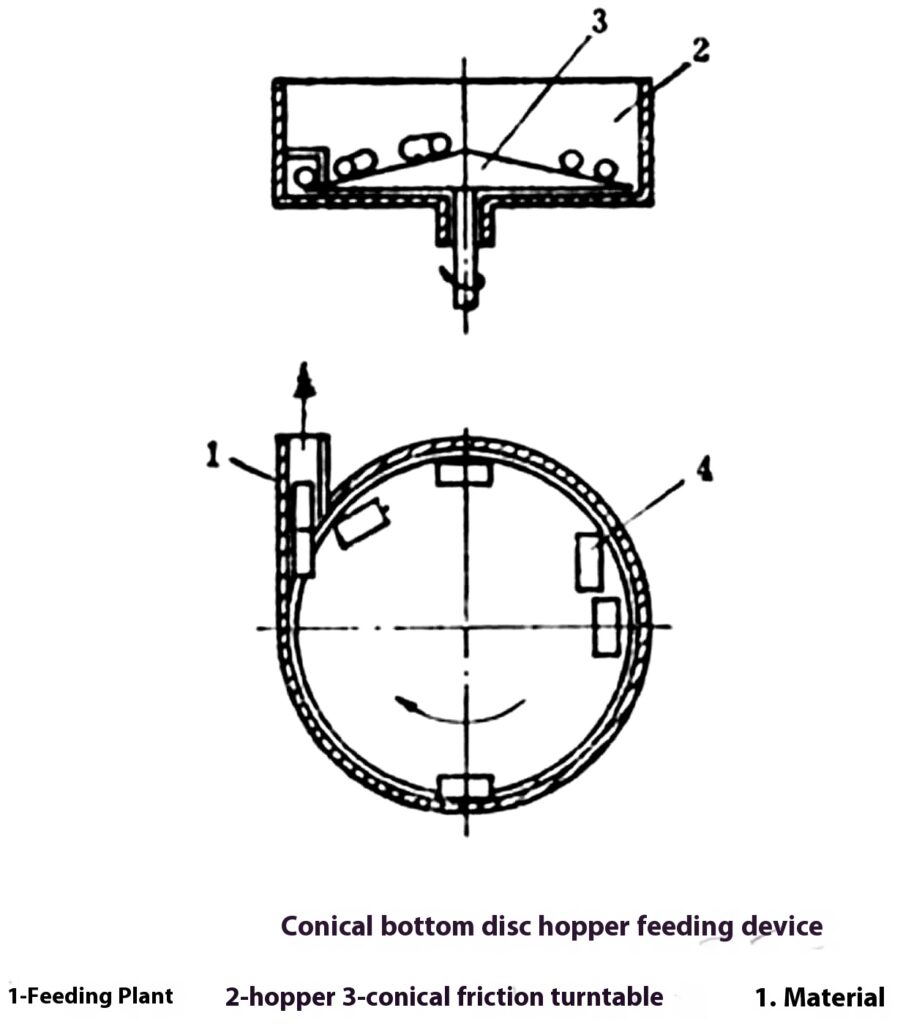
Figuren visar arbetsprincipdiagrammet för den koniska bottenmatningsanordningen för tallriken. Den koniska bottenskivan kan öka materialens tendens att röra sig till den roterande skivans ytterkant. Materialen är anordnade på ett riktat sätt längs skivans tangentriktning och kommer i tur och ordning in i transporttråget. Denna enhet har en enkel struktur och pålitlig drift. Den är lämplig för automatisk sortering och riktad matning av olika små kolonner, hylsor, lock, block och plåtmaterial.
Elektromagnetisk vibrerande matningsanordning
Den vibrerande matningsanordningen är en anordning som använder vibrationsteknik för att transportera löst pulver och små föremål på medel- och korta avstånd. Beroende på den vibrerande kroppens struktur kan den delas in i rak trågtyp och skivtrågtyp; beroende på typen av excitationskälla kan den delas in i mekanisk typ, elektromagnetisk typ, hydraulisk typ och pneumatisk typ. Här introducerar vi främst den elektromagnetiska vibrerande matningsanordningen.
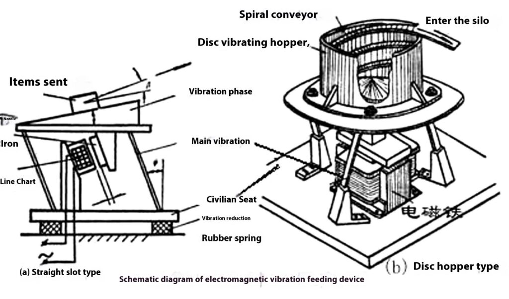
Strukturen hos den elektromagnetiska vibrerande matningsanordningen: vanligtvis sammansatt av spännande elektromagneter, armaturer, vibrerande kroppar, huvudvibrationsfjädrar, vibrationsdämpande fjädrar och baser. Som visas i figuren stöds den vibrerande trågkroppen (eller tratten) på basen av huvudvibrationsplattans fjäder, järnkärnan och elektromagnetens spole är fixerade på basen och ankaret är fixerat på botten av den vibrerande kroppen; det finns en vinkel mellan den vibrerande trågets arbetsyta och horisontalplanet (det finns en spiraltransportkanal med en spiralstigningsvinkel på a i den vibrerande behållaren), och det finns också en vinkel mellan huvudvibrationsplattans fjäder och lodplanet. Hela enheten är sammankopplad med bultar, vibrationsdämpande fjädrar och ramen.
Uppenbarligen är principerna för skivtrågtypen och den raka trågtypen i princip desamma, förutom att den raka trågtransportörkanalen ändras till en spiraltransportörkanal, och svängvibrationen ändras till en vridningsvibration.
Ta den raka tråget vibrerande matningsanordningen som ett exempel för att illustrera funktionsprincipen för den vibrerande matningsanordningen.
Som visas i figur (a) placeras föremålet i tråget. Trågkroppen utför riktad forcerad vibration under inverkan av elektromagnetisk excitationskraft och huvudvibrationsplattans fjäder. När trågkroppen rör sig till det övre högra, drivs föremålet av trågkroppen av friktionskraften och erhåller en accelererad rörelse till det övre högra; när trågkroppen bromsar upp till höger, eller accelererar till nedre vänstra under inverkan av elektromagnetisk attraktion, eftersom föremålet har fått en viss kinetisk energi vid acceleration uppe till höger, har föremålet fortfarande en tendens att fortsätta att röra sig uppe till höger eller glida en sträcka åt höger i förhållande till trågkroppens arbetsyta, eller till och med slänga den övre högra delen av trågkroppen, eller till och med slänga den övre högra rörelsen bakåt, trågets yta. När trågkroppen flyttas till det övre högra igen, accelereras föremålet av friktion igen, och ovanstående rörelsecykel upprepas. På detta sätt, varje gång tankkroppen rör sig fram och tillbaka och vibrerar en gång, rör sig artikeln ett visst avstånd åt höger i förhållande till tankens medföljande kropp, varigenom kravet på att tillföra föremål uppnås.
Vakuumanordning
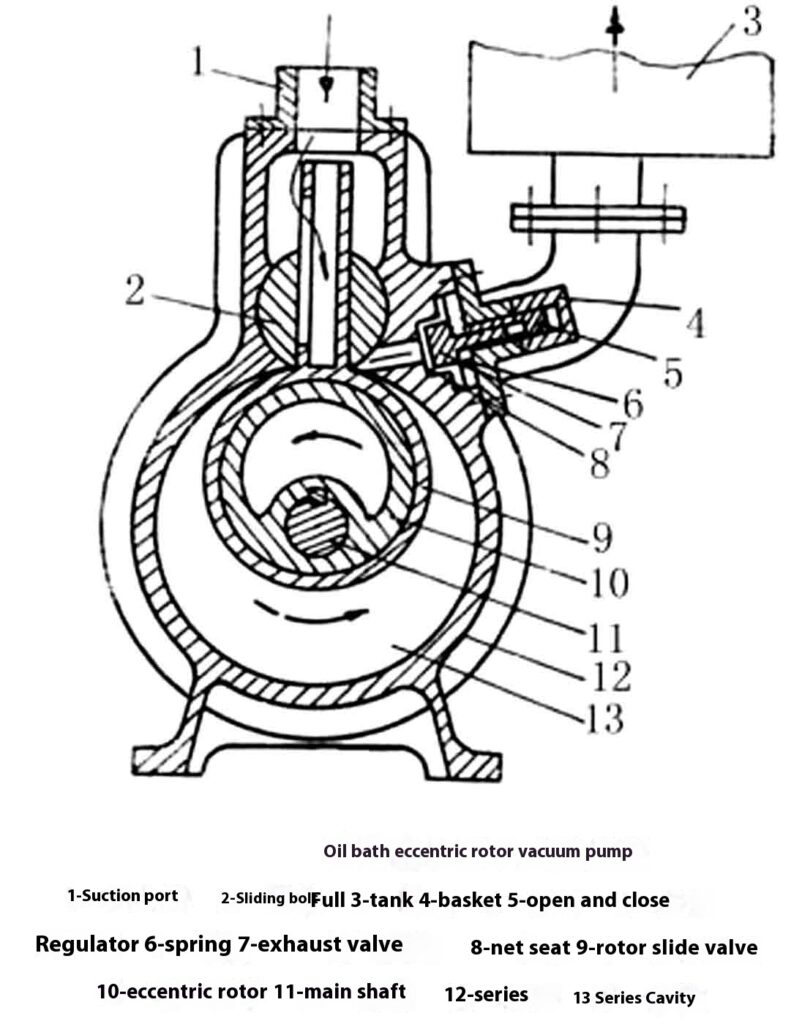
Vakuumpumpen är den huvudsakliga arbetsdelen av vakuumförpackningsmaskinen, och dess prestanda kommer direkt att påverka vakuumgraden. Det finns två huvudtyper av vakuumpumpar som används i vakuumförpackningsmaskiner: den ena är en oljebads excentrisk rotorvakuumpump (även kallad en vakuumpump med glidventil); den andra är en oljebads roterande lamellvakuumpump. Som visas i figuren.
Oljebad excentrisk rotor vakuumpump
Arbetsprincip: som visas i figuren. En rotorslidventil 9 är installerad i pumpen 12, vilken består av en ventilring och en ventilskaft. Ventilringen på rotorslidventilen är hylsad på den excentriska rotorn 10, och det geometriska centrumet av den roterande axeln 11 och pumpkammaren 13 sammanfaller. Ventilskaftet på den övre delen av rotorns slidventil kan glida fritt upp och ner i den cylindriska slidbulten 2 och svänga åt vänster och höger. Ventilringshylsan glider längs pumpkammarens 13 yta. När axeln 11 roterar moturs delar rotorslidventilen 9 upp pumpkammaren 13 i två arbetskammare, och volymen av kammare A expanderar gradvis, medan volymen av kammare B gradvis minskar. Gastrycket i kammare A fortsätter att minska och den pumpade gasen kommer in i kammare A genom hålrummet i ventilskaftet och det rektangulära hålet på sidan. När rotorns slidventil vrids till pumpkammarens 13 övre dödpunkt, slutar suget och kammaren A når maximal sugvolym, och det rektangulära hålet stängs vid denna tidpunkt. Pumpaxeln 11 fortsätter att rotera, och volymen av den ursprungliga arbetskammaren börjar gradvis minska igen, gasen komprimeras och trycket fortsätter att öka. När den överstiger fjädertrycket hos avgasventilen 7, trycker gasen upp den och töms ut. De två kamrarna A och B fungerar växelvis. När kammare A andas in, tömmer kammare B ut. Varje rotation av pumpaxeln motsvarar att slutföra en sug- och avgasprocess.
Oljebad roterande lamellvakuumpump
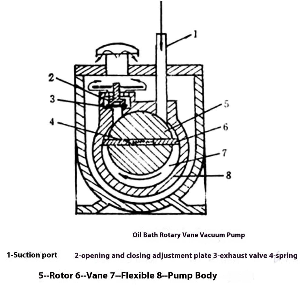
Arbetsprincip: som visas i figuren. När den excentriska rotorn 5 med två skovlar 6 roterar medurs, glider skoveln G mot pumpkroppens 8 innervägg under trycket från fjädern 4 och dess egen centrifugalkraft, och den högra sugkammaren fortsätter att expandera, och den pumpade gasen kommer in genom sugporten l. När den andra vingen passerar sugportens läge, isoleras den insugna gasen och suget är avslutat. Rotorn fortsätter att rotera, den isolerade gasen komprimeras gradvis och trycket ökar. När trycket överstiger trycket på avgasventilen 3, trycker gasen upp avgasventilen 3 genom avgasröret och släpps ut genom oljan och pumpens avgasport. Under driften av pumpen delar vingarna alltid upp pumpkammaren i två arbetskammare, A (sug) och B (avgas). Varje gång den excentriska rotorn roterar en cirkel, finns det två sug- och avgasprocesser.
Slutsats
I förpackningsprocessen spelar matningsanordningar en avgörande roll för att säkerställa smidig och effektiv överföring av material till doseringsanordningar för förpackning. De olika typerna av matningsanordningar, såsom gravitationsmatning, bandmatare, kedjetransportörer, vibrerande matare och roterande skivanordningar, är utformade för att möta de olika kraven för olika material och förpackningsprocesser. Dessa enheter måste skräddarsys för de fysikaliska och kemiska egenskaperna hos de föremål som matas för att säkerställa tillförlitlighet och förhindra problem som blockeringar eller felaktig inriktning.
Dessutom är vakuumpumpar, såsom oljebadets excentriska rotor och roterande skovelpumpar, integrerade komponenter i vakuumförpackningsmaskiner, vilket säkerställer rätt vakuumnivå för att konservera föremål. Valet av lämpliga matnings- och vakuumanordningar säkerställer en effektiv, pålitlig och säker förpackningsoperation, avgörande för att uppfylla både produktions- och kvalitetsstandarder.